
KeeYees USB Logic Analyzer Device with 12PCS 6 Colors Test Hook Clip Set USB Cable 24MHz 8CH 8 Channel UART IIC SPI Debug for Arduino FPGA M100 SCM
Product Description
KeeYees USB Logic Analyzer Device with 12PCS 6 Colors Test Hook Clip Set USB Cable 24MHz 8CH 8 Channel UART IIC SPI Debug for Arduino FPGA M100 SCM
- This kit contains 12pcs SMD IC 6 Colors Test Hook Clips which are ideal for using this 24MHz 8CH logic analyzer.
- If you are doing microcontroller, ARM system, FPGA development, we highly recommend you purchase this product! This item will help you solve your problem when you do MCU related products, especially for UART, SPI, IIC and other communication debugging.
- Compatible with the Logic analysis software and open source programs such. B. sigrok (protocol analysis of RS232, SPI, IIC, 1-Wire, etc.)
- Reliable Technical Support: We have prepared detailed tutorial, includes: guidance manual, demo code, burning tools, necessary class libraries. Please visit our website (github: Keeyees/KY-57) to get tutorial or can contact us on Amazon, we will send PDF Document to you.
<p> <strong>Feature:</strong><br /> The sampling rate of each channel is 24M/s; Actually, 10M is enough to deal with a variety of occasions.<br /> 8-channel: It can collects signals when analyzes data, such as I2C, UART, sampling and analysis.<br /> <br /> <strong>How to use it:</strong><br /> Step 1. Download sigrok PluseView (https://sigrok.org/wiki/Downloads) and install it.<br /> Step 2. Plug the logic analyzer into a USB port.<br /> Step 3. Run the Zadig driver installer (in the C: 'Program Files (x86)' folder).<br /> Step 4. Run PulseView. Connect the cable to the signal (CH0, for example) and ground pins on the logic analyzer on one end and the logic ports (digital output D3 or whatever on the Arduino) on the other end.<br /> Step 5. Write a little sketch to generate a PWM waveform on D3 and click on the "run" button in PulseView and there it is on the PulseView display.<br /> <br /> <strong>Specification:</strong><br /> Maximum sampling speed: 24Msps<br /> Input voltage range: 0~5V<br /> Digital channel: 8<br /> Input low level: <0.8V<br /> Input high level: >1.4V<br /> Support Protocol: SPI, IIC, UART, SMBus, I2S, CAN, Parallel, Custom, Search, Async, 1-Wite, PS/2<br /> Input Impedance: 1Mohm || 10pF (typical, approximate)<br /> Crystal: ±20ppm, 24MHz<br /> Error/Accuracy: pulse-width measurement: ±42ns (at 24MHz)<br /> Dimensions (LxWxH): 55 x 28 x 14 mm<br /> Dimension of test hook clip: about 5 x 1.5 cm<br /> <br /> <strong>Note: The clips require either soldering a length of solid wire (< 2 mm diameter) into which the supplied probe wires can be inserted, or by directly soldering leads directly into the clips. </strong><br /> <br /> <strong>Packing Included:</strong><br /> 1x Logic Analyser<br /> 1x USB Cable<br /> 1x 10-pin Ribbon Cable<br /> 12 x IC Hook Test Clip </p>
Technical Specifications
You might also like
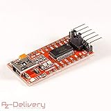
AZDelivery FTDI Serial Adapter FT232RL USB to TTL 3.3V 5V Module Mini Port for Arduino and Raspberry Pi Including Free eBook!

20PCS 2.54mm Breakaway PCB Board 40Pin Male and Female Header Connector for Arduino Shield

HiLetgo Multi-Function Shield ProtoShield Multi-functional Expansion Board Sensor Shield Module witn Four Digital Display for Arduino

HiLetgo USB Logic Analyzer Device With EMI Ferrite Ring USB Cable 24MHz 8CH 24MHz 8 Channel UART IIC SPI Debug for Arduino ARM FPGA M100 SCM

ATmega328PB Xplained Mini

Arduino Stackable Header Kit - R3
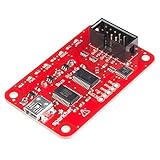
SparkFun (PID 12942) Bus Pirate - v3.6a with cable

JIUWU Test Hook Clip Ideal for Electronic Experiment

AUSTOR 840 Pieces Preformed Breadboard Jumper Wire Kit 14 Lengths Assorted Jumper Wire for Breadboard Prototyping Solder Circuits